today on the bench of healing: this Behringer S16 that decided to kick the bucket. so I think I'll take a crack at fixing it. 

symptoms are: channels 1, 7, 12, 13, and 14 have a lot of attenuation. the unit also decided to attenuate nearly every channel by 40dB during sound check.
oh that's a lot of parts. but I think I see a problem already

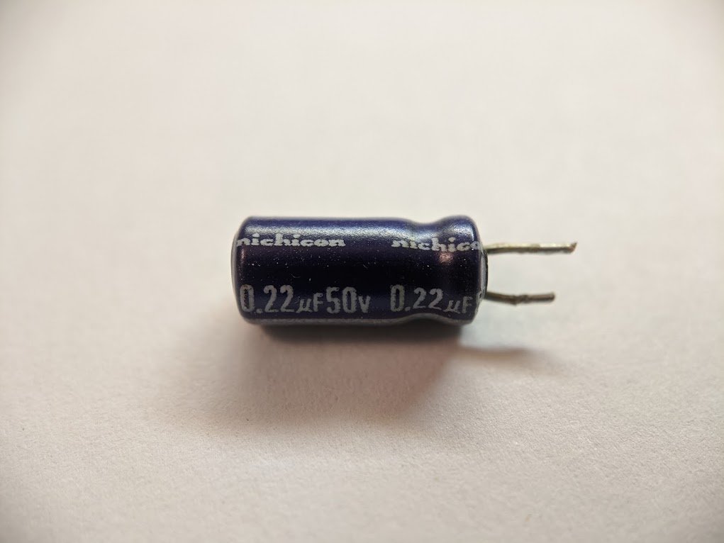
sure enough, a bulging capacitor.  this thing is only 6 years old.
this thing is only 6 years old. 
looks like I'll have to DECONtaminate it. unfortunately there are over 200 of them!

naturally there aren't any schematics or a service manual, but I have a plan
so the microphone preamplifiers are just the same circuit copied over and over again, and it honestly doesn't look that bad.

i'll just pull it into everyone's favorite open source image editing tool and start tracing it out

there, that wasn't so bad. (i did most of this yesterday)

sus
turns out it's just a clone of the venerable DG411 analog switch.

i mean this is the Behringer way™, you take a design and build it with the cheapest parts. 
after a bit of work, i now have the full schematic of the preamp. (don't worry about not being able to read it, i'll go through section by section.)

first up we have (from left to right) EMI filtering, phantom power, DC block, and ESD protection. pretty standard stuff.

then it gets interesting. this is a differential amplifier with adjustable gain. the op amps servo the transistors' emitter terminals so that their collector terminals hover at some reference voltage. basically a constant current source. R311 sets the gain.

helps to look at it 1/2 at a time. Vin-Vbe = the voltage at the center tap of the resistor divider made by R311 and R367. so it's like feeding a resistor divider backwards! gain is therefore (R311+R367)/R311.

instead of a single resistor R311, it's a parallel combination of a bunch of resistors that can be switched in and out digitally.

the analog switches are controlled by a 74HCT595 shift register, which gets data from...elsewhere. possibly the ATMega8 elsewhere on the board.
the next stage converts the differential signal to a single ended signal, attenuating and filtering it a bit.

then there's another stage with adjustable gain and some more filtering.

finally, the audio goes into a phase splitter circuit and a circuit that biases it and feeds it into a CS5368 analog to digital converter.

so where in the circuit is our little Stay-Puft™ capacitor? it's in the differential amplifier, coupling the two sections together so that we get twice the gain at audio frequencies. and it turns out this is an example of an improper use of an electrolytic capacitor...

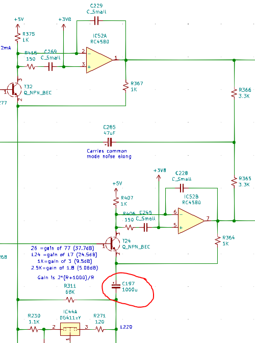
you see, electrolytic capacitors like to have a DC bias across them. this is because of their self-healing capability: any punctures in the oxide dielectric layer electrochemically react, forming new oxide. this part of the circuit does it right, with 2.5V across the cap.

this part of the circuit does it right, but only when you have phantom power turned on. otherwise those caps have a slight negative voltage across them. not great.

back to the diff amp. this 1000uF cap that failed has no DC voltage across it, ever! it'll fail early, particularly when it is warm, which it was, since this equipment sat in a rack for years with the power always on.

compare the design to this classic by Rupert Neve. he used tantalum capacitors, and every one of them has a predictable and correct DC bias.

so the "dead/quiet channel" behavior is likely caused by these improperly biased capacitors slowly failing, increasing in impedance and attenuating the input signal.
what's interesting is that a bunch of channels got quiet all at once, but later on came back after a bunch of power cycling. i suspect the ATMega8 is getting noisy power and not properly clocking the shift registers, so the wrong gain values get latched.
noisy power usually means there are (you guessed it) bad caps in the power supply.
so i have a few options here.
1) recap this thing ($100 + a few hours of labor)
2) buy a new S16 ($660)
3) buy a Midas DL16 instead ($880)
because according to the internet, the DL16 and the S16 are nearly identical. presumably the Midas has better capacitors.

unfortunately i can't tell from these potato quality photos 

for more details on electrolytic capacitors, i made a thread a while back. twitter.com/TubeTimeUS/sta…

Tube Time@TubeTimeUS
Jun 29 20
View on Twitter
today i took apart some electrolytic capacitors, and learned some surprising things. i wanted to review the manufacturing process, but let's first take apart this capacitor.
looks like the power supply has bad caps too.

yep, no good at all

the screws are stripping out. they're basically glued in with off-brand loctite. 

lack of threads. this is...bad

also it's hard to remove the caps, the leads are bent and soldered. this is going to take way too long.

so I tested all the caps in channel 1 and they were all... mostly ok? capacitance was about nominal, ESR was a tad high at around 2 ohms, but in this circuit ESR isn't terribly critical.

I fed it a signal with this DI box and it... worked fine. 30Hz to 30KHz. 

granted, I did recap the power supply. most of the caps in it were 

and poor filtering on a digital rail explains flaky behavior.
I checked all 16 inputs, and they're working fine. at least with a sine wave. and this doesn't rule out potential issues with the ADC.

Tube Time
@TubeTimeUS
vintage computers, tubes, the MOnSter6502, cross-sectioned electronic parts, capacitors, and other detritus. coauthor of https://t.co/KTJOa1Kvu6
Missing some tweets in this thread? Or failed to load images or videos? You can try to .