
Ken Shirriff@kenshirriff
Jan 23, 2023
9 tweets
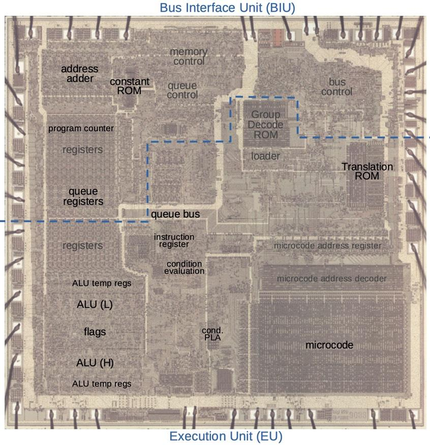
Intel's 8086 processor (1978) had a huge influence on computing. Although simple by modern standards, its die contains many different functional blocks.
Code uses conditional jumps for loops and if statements. Let's take a close look and see how these jumps are implemented.
The 8086 uses microcode, running a tiny program for each machine instruction. To keep the microcode ROM small, hardware logic helps implement instructions. The 8086 has 16 conditional jump instructions: one microcode routine implements them all, with gates handling the details.
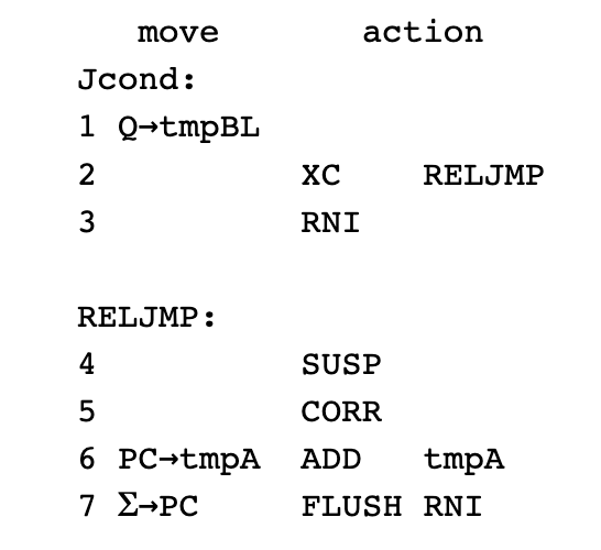
Here's the microcode for conditional jumps (Jcond). The offset goes in a temporary register. XC jumps to the relative jump routine (RELJMP) if the condition is satisfied. The offset is added to the program counter (PC) and it runs the next instruction (RNI).
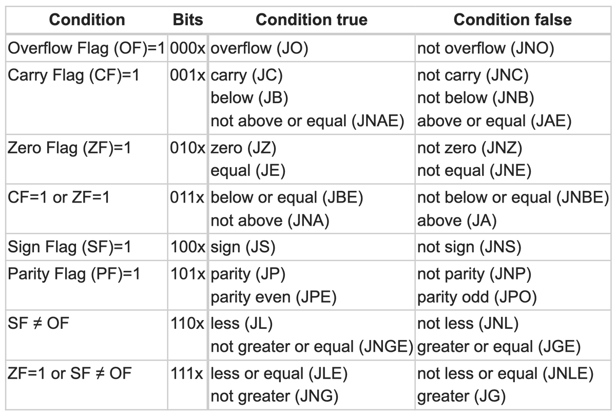
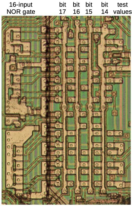
The 8086 has 16 conditional jumps. A block of circuitry decodes bits from the instruction, determines the condition, and checks flags from the ALU to see if the condition is satisfied. Putting this in hardware keeps the microcode small and simple.

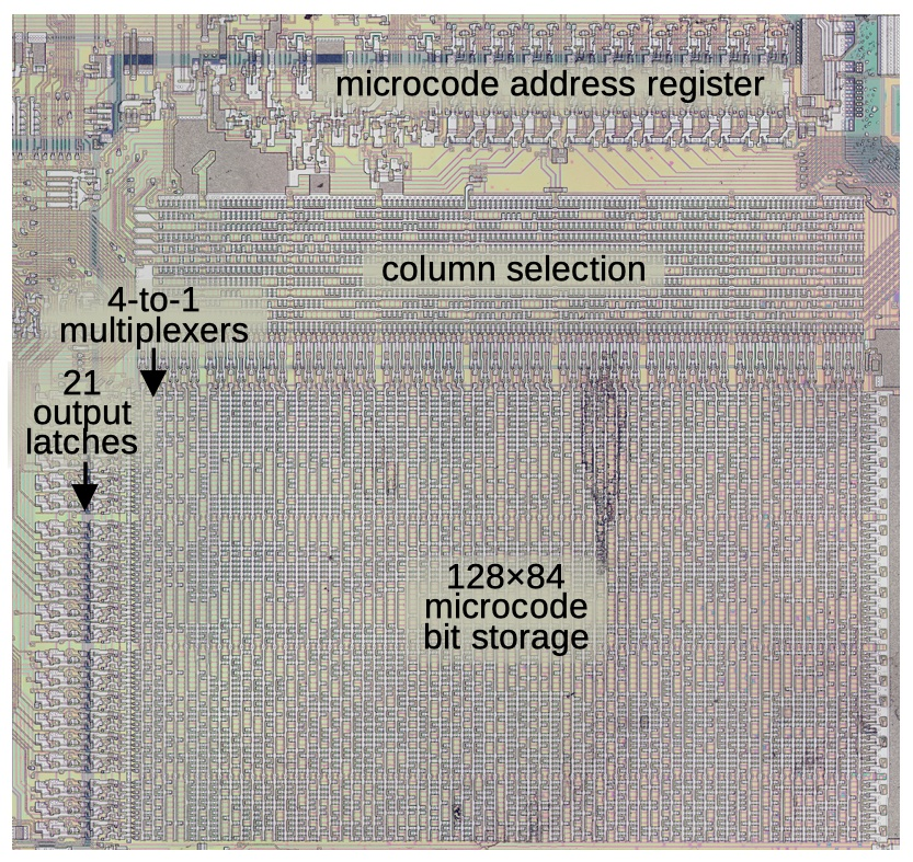
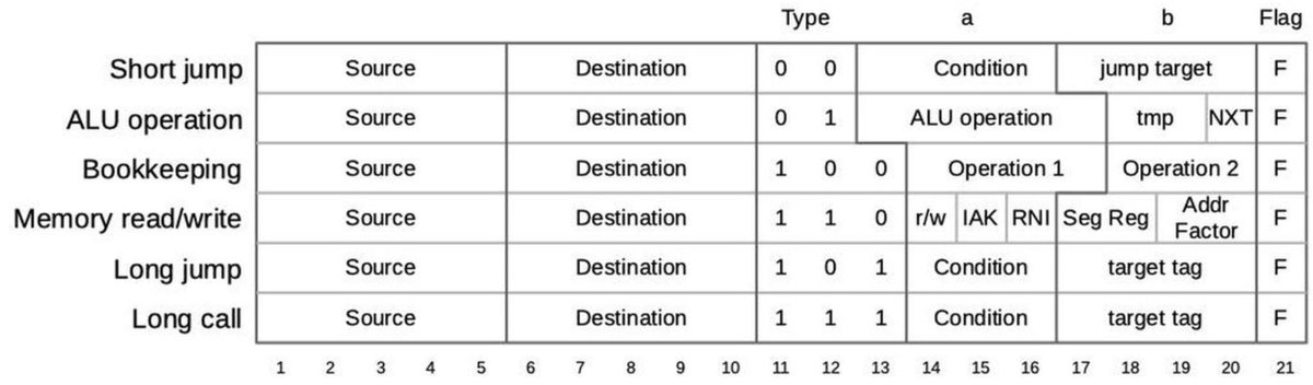
A 21-bit micro-instruction can have a condition. These are special hardware conditions, including XC. A PLA (programmable logic array) evaluates the conditions, one per row. The microcode address is updated if the condition is satisfied.
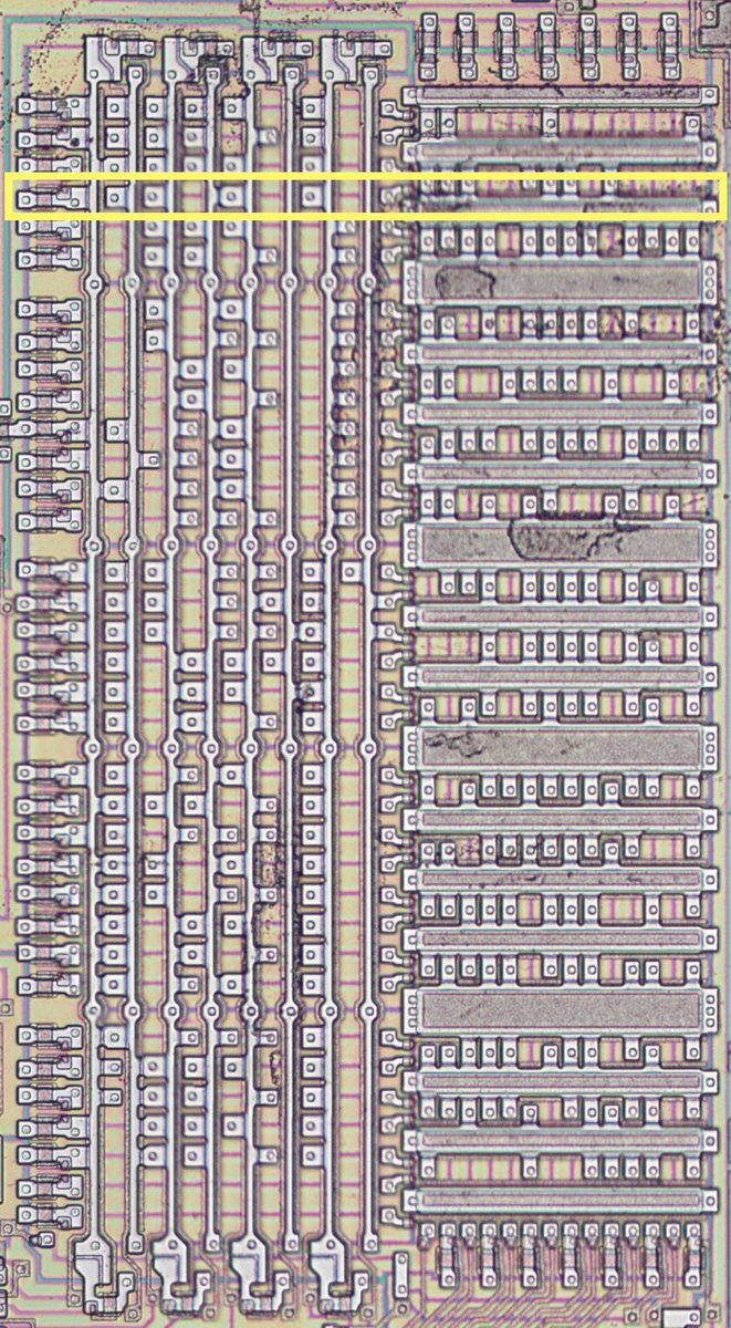
Microcode addresses are 13 bits, too big to put a jump in microcode directly. The Translation ROM converts a 4-bit tag into a 13-bit microcode address. The highlighted row is the address for the RELJMP routine.
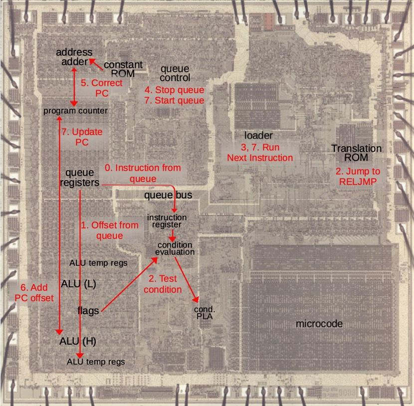
This diagram shows what happens in the chip for each step of a conditional jump. There's a lot going on. The prefetch queue adds complexity since it must be stopped and flushed for a jump. The program counter must be corrected because prefetching moves it ahead.
To summarize, microcode and special gate logic work together to compactly implement conditional jumps.
For more details, see my blog post: righto.com/2023/01/revers
Thanks to Andrew Jenner for disassembling the 8086 microcode.
reenigne.org/blog/8086-micr

Ken Shirriff
@kenshirriff
Computer history. Reverse-engineering old chips. Restored Apollo Guidance Computer, Alto. Ex-Google, Sun, Msft. So-called boffin. @kenshirriff@oldbytes.space
Missing some tweets in this thread? Or failed to load images or videos? You can try to .